Majority Vote - March 2015
Project Overview
|
The Majority Vote project aimed to make a voting system in which no votes would get over or under counted. This system consisted of a voting machine that allowed for decisions to be decided on a yes/no basis by the votes of 4 board members: the president, vice-president, secretary, and treasurer. Each member got one vote. For a decision to pass, a majority of the board members must vote yes OR in the event of a tie, the president's vote decides whether the decision passes or fails. The restrictions on the circuit allowed only the use of 2-input gates.
|

|
Problem Conception
The truth table shows the combinations of votes that would produce passing and failing decisions. To pass, as decision needs 3 or more votes. In event of a tie, the president's vote decides whether the decision passes or fails. If the president it in favor, for example, the decision would pass.
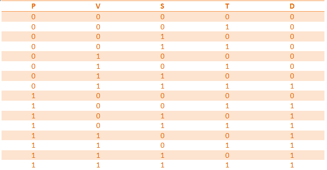
Out of a total of 16 combinations, there are eight combinations that result in a passing decisions. Six of the eight involve the president voting "yes" for a decision. There is only one instance where the president votes against a decision and it passes- when the vice-president, secretary, and treasurer all vote in favor of the decision. Four of the eight passing decisions involve a tie in which the president voted yes.
P'VST+PV'S'T+PV'ST'+PV'ST+PVS'T'+PVS'T+PVST'+PVST
Above is the un-simplified expression for the truth table. Each set of "PVST" or their inverses is a minterm derived from the truth table. Minterms occur whenever the final column is a "1" and are made up of the variables used to reach that passing decision. For example, the very first minterm is P'VST, read as not P, V, S, T. In this case, the P column has a 0, the V column has a 1, the S column has a 1, and the T column has a 1. This makes the minterm P' (becuase P is 0) VST. I used Sum of Products form because it is composed of all the minterms added together. This is, I feel, an easier form to read, understand, and gain information from.
Un-Simplified Circuit

The un-simplified circuit used 35 gates in total: four inverter gates, seven OR gates, and 24 AND gates. This would require the use of nine chips: seven AND chips, two OR chips, and one inverter chip. If this circuit was constructed, it's breadboard would be quite crowded. But, with the use of Boolean algebra, this circuit can be simplified immensely.
Boolean Algebra Simplifications
The lengthy expression given above can be simplified to a much shorter and efficient statement using Boolean Algebra.
VST+PV+PS+PT
P'VST+PV'S'T+PV'ST'+PV'ST+PVS'T'+PVS'T+PVST'+PVST
PV'ST'+PV'ST
PV'S(T'+T)
PV'S(1)
P'VST+PV'S'T+PV'S+PVS'T'+PVS'T+PVST'+PVST
PVS'T'+PVS'T
PVS'(T'+T)
PVS'(1)
P'VST+PV'S'T+PV'S+PVS'+PVST'+PVST
PVST'+PVST
PVS(T'+T)
PVS(1)
P'VST+PV'S'T+PV'S+PVS'+PVS
PV'S'T+PV'S
PV'(S'T+S)
PV'(T+S)
P'VST+PV'T+PV'S+PVS'+PVS
PVS'+PVS
PV(S'+S)
PV(1)
P'VST+PV'T+PV'S+PV
PV'T+ PV
P(V'T+V)
P(T+V)
P'VST+PT+PV+PV'S
PV+PV'S
P(V+V'S)
P(V+S)
P'VST+PT+PV+PS
P'VST+ PV
V(P'ST+P)
V(ST+P)
VST+PV+PT+PS
Simplified Circuit
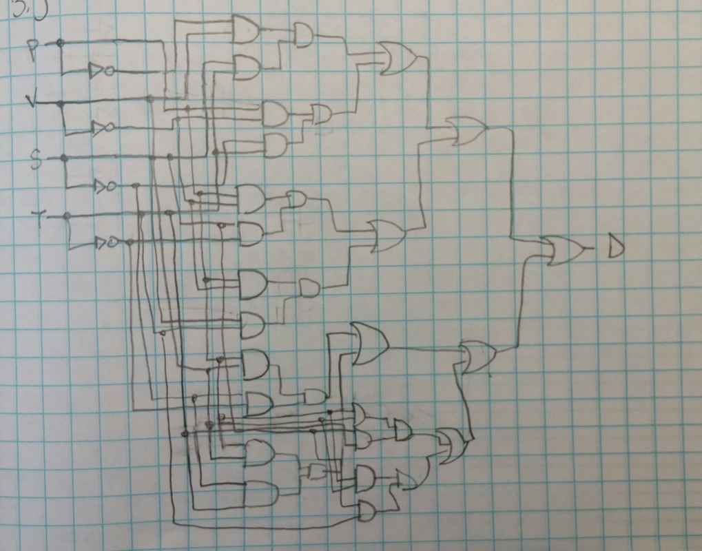
These images show the hand-drawn and MultiSim schematics for the simplified circuit. As you can see, these circuits are much smaller and easier to understand that the previous circuits.


This circuit uses way fewer gates. Five AND gates, three OR gates, and no inverter gates are used. This would allow for the use of just three chips, two AND chips and one OR chip, as there are only four gates per chip. With a more simplified circuit, everything is easier to understand, cleaner, more organized, and produces a result much more quickly.
The simplified version used far fewer gates and chips that the un-simplified version. The simplified version eliminated the use of 27 gates and six chips. Using fewer chips allows for a cleaner-looking, uncomplicated circuit. Having an uncomplicated circuit allows for the current to pass through more quickly, Another benefit of having a simpler circuit is that it allows mistakes to be found more easily.
Bill of Materials
A variety of different materials were used to build the circuit.

To make the circuit, I used the materials above. The resistor was 3.3 KOhm. I used two AND chips because with five AND gates needed, they wouldn't all fit on one chip. Wires were used to connect all the different components.
Bread-Boarding

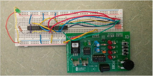
S1 represents P, S2 represents V, S3 represents S, and S4 represents T. The orange wires seen here connect E to F, allowing enough room to connect all the necessary wires to the chips.
|

This is one side of the row of chips I used. The one to the far left is the OR gate, the other two are the AND gates. The short blue, yellow, and white wires connect the chips to the power.
|

This is the other side of the row of chips. The one to the far right is the OR gate. The three blue wires connect the chips to the ground.
|

Shown here is the top of the breadboard. The red and yellow wires connect the left side of the breadboard to the right side. The green LED is the indicator of whether or not a decision passed.
|
|
To the left is the whole breadboard. Unfortunately, it looks quite messy due to the distance between where S1, S2, S3, and S4 are and where the chips are, but this was unavoidable for the most part. |
I was very excited when I tested my circuit, as it worked the very first time. When I breadboarded, I was very systematic. First, I connected both sides and grounded and powered all of my chips. Then I worked on each minterm one at a time so none would get skipped or done twice. By thinking through what I needed to do and remembering what we did in class, I was able to complete my circuit quite easily.
Final Project Conclusion
This project demonstrated how to design, simplify, and build a circuit from a problem statement. To do this, you first construct a truth table, extract the minterms to create a logic expression, and form a circuit from that expression. You can then use Boolean Algebra to simplify your logic expression. Then, using the new logic expression, you can design a simplified circuit. After designing the simple circuit. it can be built on a breadboard. Boolean Algebra is useful when the original logic expression is very long and complex, like in this project. Boolean Algebra simplifies the expression so that the circuit can be built without the use of an extravagant amount of wires and chips. The simplified expression is equivalent to the simplified one, but is easier to understand and design a circuit around.
